Power over Ethernet (PoE) continues to advance. According to studies, the number of PoE-capable ports has tripled in the past five years. Network cables that can transmit more and more power are driving the trend.
One Technique, Many Advantages
Originally developed to power classic telephones, PoE is becoming increasingly important in other areas as well: Internet of Things (IoT), smart office and residential cabling and many network-compatible devices in offices and industry. PoE transmits power and data over a single cable, saving the cost of purchase and operation of additional cabling.
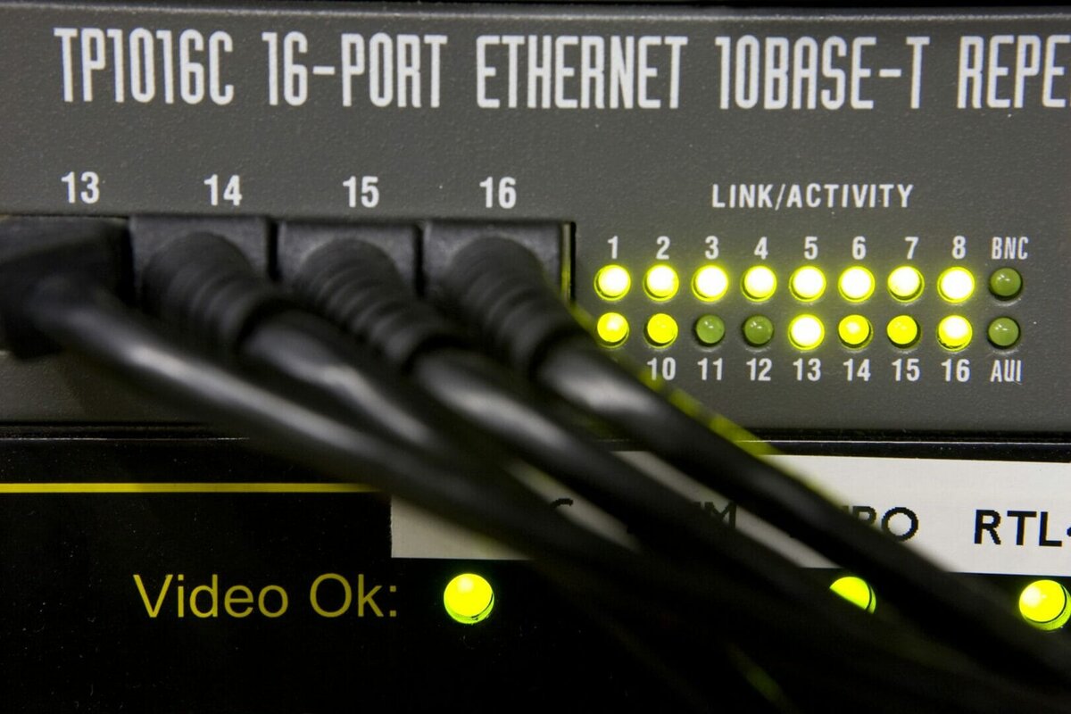
PoE injectors or switches/hubs serve as the power source. Companies use this technology to supply remote devices such as webcams, surveillance cameras or WLAN access points, often installed in inaccessible places. Another advantage of PoE is the increased reliability of the connected devices via a central and uninterruptible power supply (UPS). Continuous operation is possible in the event of a power failure.
PoE Standards: A New and Exciting World of Opportunity
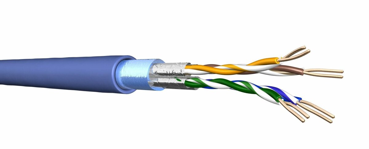
Two variants are available for the transmission of energy between the energy supply (Power Supply Equipment, PSE) and the energy consumer (Powered Device, PD). The spare pair procedure uses only the free wire pairs 4/5 and 7/8 for the power supply between PSE and PD. With phantom power, the voltage is supplied via all wire pairs, which are also used for data transmission. This means that the current flow is over the data line.
The latest standard, IEEE 802.3bt, specifies the maximum achievable power over four-pair PoE, at between 72 and 90 watts. Thanks to this higher performance, even larger end devices, for example IP TV devices in Full HD, can now be supplied with energy via a data cable. Cable manufacturers are continuously working to further develop the PoE performance of network data cables, recognising the limited power output that the PoE process entails is still the biggest shortcoming to the wider adoption of the technology.
Heat Management of PoE on Cabling
The addition of electricity means an increased load for the cable/link/channel, which usually results in increasing cable bundle temperature. The greater power a data cable delivers, the more heat is generated in the cable. It is a cable’s ohmic resistance that generates heat, 25Ω/100m being the maximum channel. In addition, the bundle size and installation environment directly influence the cable’s heat dissipation leading to significant temperature increase.
Special care needs to be paid to patch cords. A channel, which includes two/three patch cords with smaller conductors (higher resistance) than the cable could lead to the possibility of even higher temperatures being generated.
The type of cable pathways used is a decisive consideration here: grid cable pathway, perforated cable system or completely closed duct pathway made of plastic will have significantly different effects on temperature. Cable laid on open grille clearly keeps cooler through air flow compared to closed duct. The standard EN-50174-2 states under 4.5.4.2 that the degree of filling should not exceed 40%. Correct planning, maintaining and execution of the installation will have a direct influence on the cable’s PoE performance.
When planning for PoE applications, heat management of the cable channel must be a top consideration. Continual heating and cooling over time will change the cable’s performance. Replacing a patch cord with a product that is smaller in copper size and/or increased in length could change the stability of the bundle/installation, or even the whole system.
Heat build-up over a PoE channel can also negatively impact the connectivity components. There is a real risk that if disconnected under load a spark can be generated which could destroy contacts.
Increase PoE Efficiency
4 pair cables maximum operating temperature is 60°C. If the temperature exceeds this limit, transmission properties decrease, along with softening of the insulation material and associated permanent structural symmetry loss.
Optimising the efficiency of a PoE channel requires consideration of the maximum operating ambient temperatures of both the cable (60°C) and the components (50°C). Other factors that need to be considered are power loss and heat dissipation.
This leads to the calculation:
50°C maximum ambient temperature + power loss – heat dissipation = < 60°C maximum heat limit
To achieve this optimum performance the total heating effect from power loss versus heat dissipation therefore must not combined exceed 10°C.
To maintain this operating limit of 10°C, the power loss must be reduced, or the heat dissipation increased. The amount of power loss depends on the current, resistance and the PoE pairs used. Other factors which influence the heat dissipation include bundle size, patch-cords, shielding and air flow.
How Do You Reduce Power Loss?
The key consideration is DC loop resistance, the higher the loop resistance the less flexibility is available to the designer. A cable with a 24 AWG conductor, typically Cat.5e, will have a DC-LR of 173.86 Ω / km.
A cable with a 22 AWG conductor, or 0.645mm, typically Cat.7a will have a DC-LR of 108.70 Ω / km. This gives an operating range that is 60% higher than AWG 24. Put simply, larger conductor diameters improve the PoE range twofold.
How to Increase Heat Dissipation?
In addition to a larger conductor diameter, shielded cables also have a positive effect on heat dissipation. The metal of the shield helps to dissipate the heat generated inside. Smaller bundles and greater flowing air currents also promote heat dissipation. Shielded cables allow greater flexibility in heat management at the design stage.
Planning Guidelines
Table 4 from EN 50174-2 illustrates how temperature increases the effect of the transmission path.
To achieve the same transmission performance as a cable channel consisting of a 90 metre permanent link and 10 metres of patch cords operating at an ambient temperature of 20°C, the same channel at 60°C would need to be 20% shorter. This very clearly illustrates the importance of heat management at the planning stage. As previously stated, poor planning or changing patch cords with smaller conductors will further impact this effect. Patch cords with a conductor of less than 26 AWG should always be avoided.
Essential Bundle Testing
To further illustrate the importance of the cable’s conductor size to the impact of heat management, ISO / IEC TR 29125 conducted additional testing of cable bundles at 1000 mA per pair.
It was found that in the case of 24AWG (Cat.5e) conductor size, the maximum bundle size at the 10°C limit was 37. Within the same testing scenario, cables with 22 AWG (Cat.7a) conductors could be placed into a bundle of 64 cables before reaching the critical value of 10°C.
Conclusion
All cable categories from Cat.5e to Cat 8.2 support the PoE standard 802.3af, at and bt. However, when the critical impact of heat generation and consequently the need for heat management are taken into consideration, there are significant differences between the maximum bundle sizes that can be used and the maximum drive distances that can be achieved. It is clearly the case that the larger the conductor size and the shielding of the cable, the more flexibility is available at the planning stage, and a final repeat warning on the choice of patch cables both at planning and on-going maintenance.
Draka is a brand of the Prysmian Group, the world market leader in power and telecommunications cables and systems. mms.drakauk.com